Create Neural Network force field of Ag-C system#
This article is based on data provided by Associate Professor Osamu Kurokawa (Graduate School of Engineering, Kyoto University).
Overview#
The behavior of carbon adsorbed on Ag surface was analyzed with a Neural Network force field. First, Neural Network force field was created for structure with multiple C atoms adsorbed on the Ag(111) surface and structure with C atoms located at sublattice points in an atomic layer slightly inside the Ag surface. Monte Carlo simulation was performed using the created Neural Network force field to analyze the distribution of C atoms near the Ag(111) surface.
①Sample Structures#
The following 22 sample structures were used to create training data.
②Random Structures#
Random structures were generated based on the 22 sample structures. The method and the number of generated random structures were as follows.
-
For all 22 sample structures, the atomic coordinates were randomly displaced (displacement width: 0.2 Å). → 4,400 structures were generated.
-
For sample structures consisting only of Ag atoms or C atoms, trajectories of MD calculations using EAM and ReaxFF force fields were included in the random structures. → 1,000 structures were generated.
-
Random structures were generated by reinforcement learning for the systems with C atoms adsorbed on the Ag slab model and for some of the systems (#13, 14, 19, 20, 22) containing C atoms as sublattices. → 2,000 structures were generated.
Out of the total of 7,400 structures, those for which SCF calculations converged successfully and the maximum force was less than 10 eV/Å were used to train the Neural Network. The number of structures used was 4,744 and the total number of atoms was 630,469.
③Training Data Generation with First-principles Calculations#
Training data was generated with Quantum ESPRESSO. The calculation conditions in SCF calculations were as follows.
| # | The Calculation Conditions | set value |
|---|---|---|
| 1 | pseudo-potential | Ultrasoft-Type (Ag.pbe-d-rrkjus.UPF, C.pbe-rrkjus.UPF) |
| 2 | Exchange Correlation Functional | GGA-PBE |
| 3 | Spin polarization | None |
| 4 | Wave function cutoff | 25Ry |
| 5 | Charge density cutoff | 225Ry |
| 6 | k point sampling | Only Γ point |
| 7 | Smearing | Gaussian (0.01Ry) |
| 8 | Convergence threshold | 10-6 Ry |
| 9 | lattice constant | Use values obtained from Materials Project |
④Neural Network Force Field Creation#
A Neural Network force field was created with the following specifications.
- Chebyshev polynomial was used for the symmetry function. The cutoff function was composed of tanh3 and the cutoff radius was 6 Å. The number of symmetry functions was 60 for the radial component and 40 for the angular component.
- The structure of the Neural Network was 2 layers x 50 nodes and the activation function was tanh.
- A full batch algorithm was applied and optimization was performed using L-BFGS method.
- After the calculation of 10000 epochs, the RMSE for energy was 0.027 eV/atom and the RMSE for force was 0.15 eV/Å.
⑤Monte-Carlo Simulation#
Monte-Carlo simulation was performed with Metropolis method using created Neural Network force field.
Analyical Model
face_8x4√2slab_model.png)
Metropolis Method
Simulation video
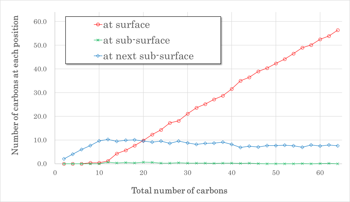
Location of C atoms

- C atoms existed on the surface or the next sub-surface and rarely on the sub-surface.
- When the number of C atoms was smaller than 20, C atoms were preferentially in the next sub-surface.
- When the number of C atoms was greater than 20, the number of C atoms in the next sub-surface tended to decrease slightly. Instead, the number of C atoms on the surface increased linearly.
- The limit number of C atoms that could enter the next sub-surface was about 8, and all of excess C atoms above that existed on the surface.
_AgCrystal_FCCstructure.png)
_diamond.png)
_graphite.png)
_Wurtzite_type_alloy.png)
_Rock-salt_type_alloy.png)
_diamond_type_alloy.png)
_Ag-Crystal_w_point_defect.png)
_diamond_w_point_defect.png)
_graphite_w10per_defect.png)
_AgCrystal_w_C@secondary_grid(40atom).png)
_AgCrystal_w_C@secondary_grid(36atom).png)
_Ag(111)_surface.png)
_Ag(111)_slab_w_C@secondary_grid(100atom).png)
_Ag(111)_slab_w_C@secondary_grid(108atom).png)
_Ag(111)_surface_w_C@top.png)
_Ag(111)_surface_w_C@bridge.png)
_Ag(111)_surface_w_C@hollow.png)
_Ag(111)_graphite(186atom).png)
_Ag(111)_graphite(153atom).png)
_Ag(111)_graphite(136atom).png)
_Ag(334)_surface.png)
_Ag(334)_surface_w_Catom@hollow.png)